Micro molding PEEK Components for Medical Implants
Polyetheretherketone (PEEK) continues to gain acceptance for use in implantable devices, in some cases replacing metals. This is due to its superior biocompatibility when compared with metals and mechanical properties approaching some metals (figure 1). Correctly compounded, some filled grades can mimic the modulus of bone tissue, slowing or preventing atrophy of bone at the interface of the prosthesis. Orthopaedic device designers have led the charge in the use of PEEK, but other biomechanical designers are taking advantage of its properties.
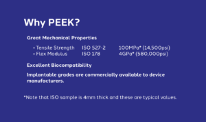
Figure 1: Typical PEEK Properties, high flow.
In addition to its mechanical properties, PEEK has another advantage. It is a thermoplastic that can be injection molded. Molded PEEK components are a fraction of the cost of machined components, whether metal or machined from PEEK bar stock. There are two barriers to this cost saving. First, there is the capital investment of the mold. Even by micro mold standards, PEEK molds are expensive. Second, the component design must be adjusted to be injection molded. Often this is not done and as a result many projects have failed and the material blamed as not moldable.
There are several difficulties in molding PEEK. These must be accommodated and accounted for in the design of the component and the mold. The melt process temperature of PEEK is 400˚C. To achieve high crystallinity, the mold temperature must be in the 200˚C range. PEEK’s low apparent viscosity makes it prone to flashing. Upon solidification in the mold, PEEK adheres to the mold surface. In other words, it is literally glued to the mold.
There are some additional considerations with micro molding. At the micro level, published material strength standards become unreliable. This applies to tool steel as well as plastic resin. Small (<0.25 mm) core pins and ejector pins become more fragile and lose their stiffness. This is a consideration for the mold designer. Due to the reduction in the polymer strength, defects such as voids and weak knit lines have a greater impact on part failure. It is best to assume 50 percent reduction in properties, design for that, then test, test and test again. The shear rates that occur in micro molding make the process more flash prone.
So, how are these difficulties overcome? This article begins with the molding process, then works back through mold design and finishes with part design.
Impact of the molding process
The molding machine needs to be configured for high temperature processing. This means correct material selection for plasticising components, heater bands and a temperature controller that allows for the required 400˚C melt. Most high-end machine manufacturers have a high-temperature option that meets these requirements. Due to the high apparent viscosity of PEEK combined with the shear effect of micro molding, precise control of injection speed and pack profiling is needed. Plastic Design Company (PDC) has had good success using electric servo controls.
There is a great deal of debate as to the best design for plasticising and metering plastic for micro PEEK molding. There is the reciprocating screw camp and the screw/plunger camp. Each system has its drawbacks and there are machine manufacturers of each design that have overcome these drawbacks.
PDC opted for the reciprocating screw because of having the greater experience of this design and an understanding of what needs to be done in order to achieve shot consistency. It has also proved the easier of the two to clean and maintain, which is critical for implantable molding. All of PDC’s machines have 14mm screws, the smallest size capable of consistently plasticising commercial pellets.
Impact of the mold design
Some of the problems encountered in molding PEEK can be overcome at the mold design stage. The high mold temperature required to achieve crystallinity poses challenges in terms of both temperature control and thermal expansion. Cartridge heaters are typically used to get the mold up to temperature. The heat absorbed by the mold during polymer solidification is radiated from the mold’s exterior surface to the ambient air.
![]()
![]()
The goal is to achieve dynamic thermal stability as quickly as possible. This is best accomplished by keeping the mass of the mold as low as possible. In the case of micro molds, this happens naturally. Also, the heating elements should not be placed in the mold base steel. The steel of the mold base is a relatively slow thermal conductor, and this leads to bands of heat moving through the mold, causing inconsistent processing. The solution is to place the heating elements into a high thermal conductive material to create planar transfer of the heat for uniform temperature (figure 2).
Figure 2: Heat transfer, left: through steel plate, right: through conductive plate.
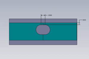
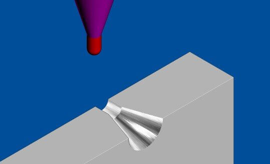
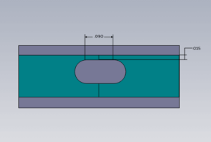 In some instances, it may be necessary to manage heat in an isolated feature of the mold such as a thin core feature. The heat can be drawn out by creating a thermal gradient such as an insulated heat sink. However, a better solution is to eliminate the need for a high-aspect ratio core feature in the mold. This needs to be dealt with as a product design issue. A recent example of how PDC handled this is illustrated in figure 3. Even though the thin core could not be eliminated, by reducing the aspect ratio, it was possible to prevent the core steel from overheating. Mold designers must pay careful attention to the coefficient of thermal expansion of the various materials they are using to maintain correct fits at temperature. This is especially true if designing with thermally conductive materials.
The high apparent viscosity of PEEK can help and hinder at the same time. Thin, long features can be molded, but PEEK can also flash easily. Gaps of 0.01 mm will flash. A carefully constructed mold with close fits on all working components is therefore required. There is a fine line between tightly fitting the mold and adding proper venting to prevent gas trapping. Gas trapping leads to weak knit-lines where flow fronts meet and surface and/or internal voids. Adding laminations to the mold design provides seams that deliver venting away from the parting line. Figure 4 shows a void that occurred on a thread feature. In Figure 5, a lamination insert has been added to create a seam that allows gases to vent, eliminating the void. PDC typically uses 0.005 mm vents.
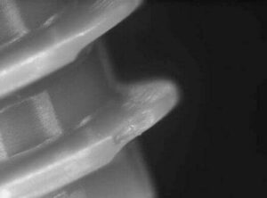
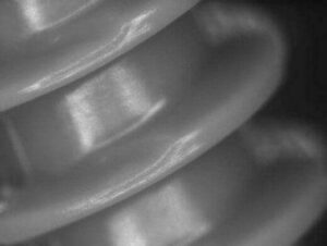
Figure 4: Void on thread feature. Figure 5: No void on thread feature after vent lamination.
After the part has solidified, it needs to be removed from the mold without distortion. There are three key considerations for this:
- The part must have adequate draft. PDC nominally requires three degrees. There are some cases where as little as half a degree has worked, but those were special cases where there had been excellent ejection and strong part geometry.

- The mold must have a suitable surface finish. PDC uses an SPI A3 finish on all surfaces, having found that it provides the best release of the plastic from the mold surface.
- The design of the ejection should be regarded as critical. Micro parts often lack the flat surfaces to get adequate ejection. Nonetheless, ejection is still required. Delicate parts need to be ejected under deep features, not from surfaces higher in the draw (figure 6). The only dimensional issues PDC has encountered with molding PEEK have been due to distortion on ejection.
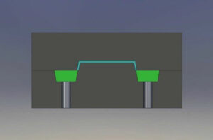
Figure 6: Optimized ejection
Impact of the part design
A highly recommended start is the adoption of the best design practices taught by Glenn Beall1 in the 1970s and 80s. The rules he outlined then are just as applicable today. It is even more important to follow them as the micro molding envelope is pushed through the use of exotic materials.
Maintaining uniform wall thickness allows for uniform solidification, lower internal stress and less likelihood of voiding. Another problem attributable to varying wall thicknesses is the impact on fill progression. This can cause stalled fill as well as cold knits that degrade the integrity of the finished part. Even under magnification, a cold knit in PEEK looks great, but it is going to crack under load. Figure 7 shows a solution used to eliminate intermittent thin sections created by a drive feature on a cylindrical part. In figure 8, by simply adding larger corner radii, the thin section is eliminated, allowing for a more uniform fill.
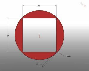
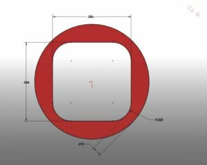
Figure 7: Intermittent thin wall sections. Figure 8: Improved design for intermittent thin walls.
Gate location and injection speed can impact the fill pattern, but variation in wall thickness will have a greater impact. Avoid thick intersections, as this leads to sinks, voiding and distortion. Use radii to reduce stress risers. PEEK is fairly notch sensitive. Careful design of fillet radii reduces corner stress, aids in mold release and helps in wall thickness transitions. In the mold design section, draft should be emphasized, but the part designer needs to allow for it. This can be tough on micro parts. Wall sections are thin to begin with. Adding draft often makes this worse. It should be remembered that if the part cannot be removed from the mold without distortion, there is no part, and getting the draft in the design pays dividends.
Case study—bone anchor lamination demonstration
One of the challenges in micro molding is getting crisp edges. Plastic only flows so well into a corner. In the case of orthopaedic fixation devices, serrations formed by sharp edges are used to hold the device in place. The question always arises as to how sharp a corner can be molded. Through the use of mold laminations, a clean sharp corner can be achieved, however this can quadruple the price of the mold.
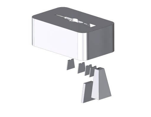
To help customers in the decision-making process, PDC has built a two-cavity bone anchor. One cavity was constructed in the solid using electrical discharge machining (EDM) to form the barbs of the anchor. In the other cavity, a separate steel lamination was created for each barb (figure 9).
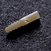
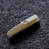
As can be seen, to accurately fit these parts together required some high technology machining. First, hardened steel was high-speed machined to generate the molding surfaces of the barb (figure 10). To keep the insert rigid, it was left 1.00 mm thick. After milling, it was wire electron discharge machined to shape and a thickness of 0.25 mm (figure 11). The results can be seen by comparing the part from the solid cavity (figure 12) and the part from the laminated cavity (figure 13).

In summary, PEEK can be successfully micro molded in intricate geometries. Best practices must be followed in part design, mold design and manufacturing. Parts must be designed for the micro molding process.
Reference
1Glenn Beall is widely recognized for contributing to the advancement of plastics design. He obtained a BSc degree from Bradley University before pursuing a career in the plastics industry that spanned many roles, including engineer, inventor, consultant, educator, author, editor and activist. Beall has also been a hugely active and influential member of the Society of Plastics Engineers (SPE) and Plastics Industry Association (PLASTICS).